Thursday, July 28, 2005

Final Project, aka Midterm Upgrade

Upon completing the Midterm, Lazlo and I discussed plans for the final project. We definately wanted something that sounded more like an actual musical instrument. It was decided that we would try to integrate the use of a MIDI synthesizer. In addition, instead of using the same switches from the midterm, we are going to be making a glove/orb switch (refer to pictures).

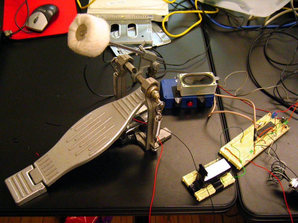
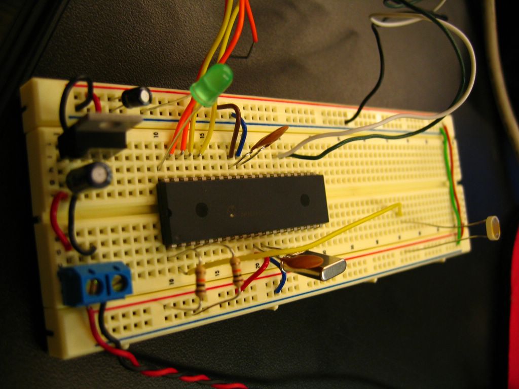
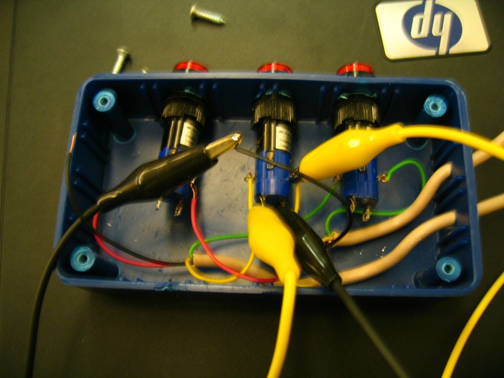
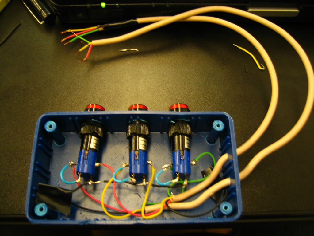
We put together our MIDI test board and was able to successfully play notes with the different switches (represented by header pins and alligator clips). Refer to Lazlo's code for more details.
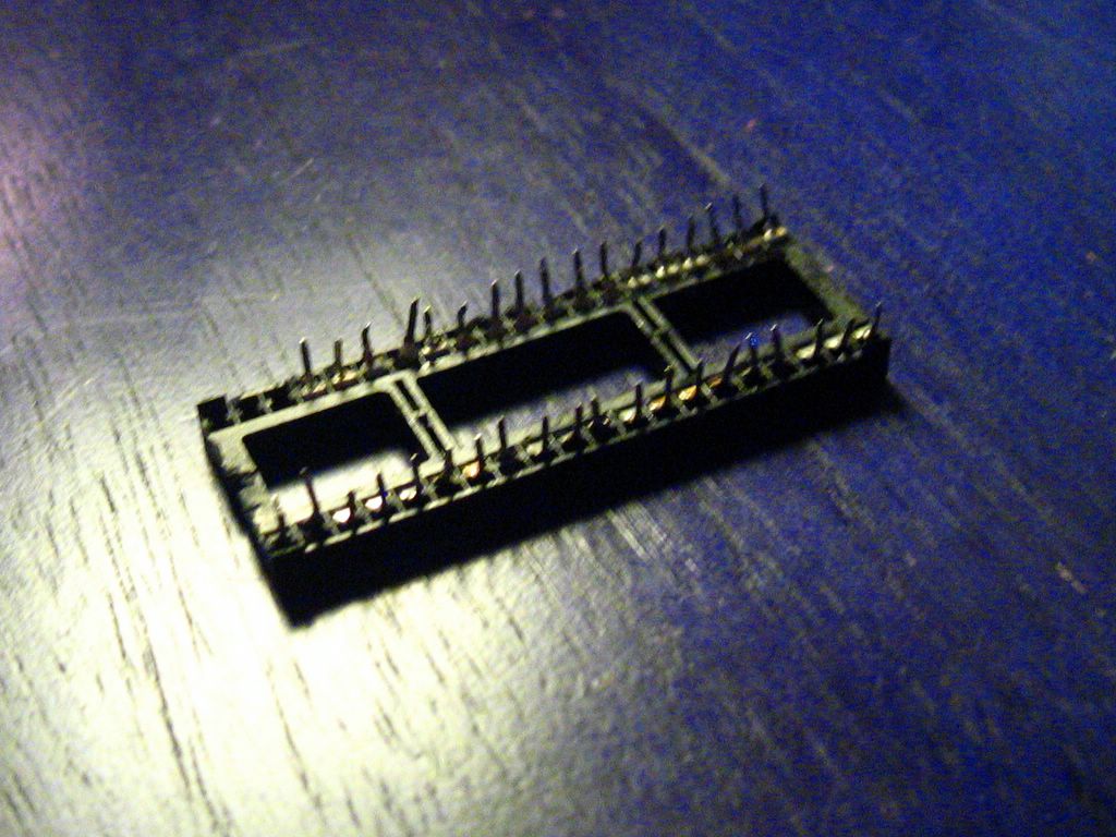
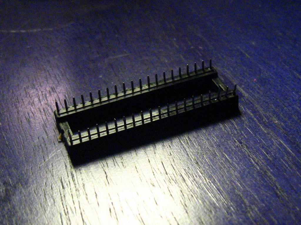

MIDI test board Posted by Picasa


A closer look at the MIDI test board Posted by Picasa

Now, for the switch we will be outfitting a glove with metal contacts that will touch an orb to complete the circuit. LEDs will be used to verify with the user with button is making contact.


If your hand looked like a bear claw...Posted by Picasa


Diagram of orbPosted by Picasa


Bear claw playing orbPosted by Picasa

So far, we have clustered all of the LEDs, tested that the system will work and soldered together with the help of some perf board. The cluster was tested using a battery pack which consisted of 3 AA batteries and alligator clips. The cluster shares ground and their other end will be connected to their respective metal contact. Note that the "blue LEDs" are not LEDs. The are the incandescent light bulbs off of some old strand of Christmas lights.


LED cluster Posted by Picasa


Red Posted by Picasa


Green Posted by Picasa


Yellow Posted by Picasa


Blue Posted by Picasa

Our next step is to find a glove that will be flexible enough to make for comfortable playing of the orb. We're looking into welding gloves or latex dish washing gloves.

Thursday, July 21, 2005

Midterm Video

Video goodness here and code for your viewing pleasure at Lazlo's Blog.


It's DEVO-like! Posted by Picasa

Wednesday, July 20, 2005

Completed Midterm Project

After using Jun as a guinea pig, she gave us some great suggestions as to how to make our controls more user friendly including her suggestion that we use a foot pedal for our play/stop button to mimic playing a piano. Luckily, I had a foot pedal from a drum set. After making the adjustments, this is what we got:


Complete circuit Posted by Picasa

To make the foot pedal a switch was a bit tricky since basically the whole pedal is conductive. With some strategically placed electrical tape, I was able to make a pretty fancy switch.


Play/Stop foot pedal Posted by Picasa

Here is a close-up of our breadboard.


Breadboard  Posted by Picasa

We enclosed the photocell to give us the ability to limit the amount of light that was received on the cell which controls the tone that is played. Using a metallic box further helped us get a wider range of values.


Tone photocell in sliding case Posted by Picasa

My three button switch was reduced to one button. One of the buttons function was redundant so it was removed and the other one was replaced by the foot pedal. For those interested, the funky shaped speaker was taken from a G3.


Note duration/frequency switch and Speaker Posted by Picasa

Video to be posted. In the meantime, here are some photos of Lazlo demonstrating how the instrument is played.


Lazlo playing instrument (Pic 1) Posted by Picasa


Lazlo playing instrument (Pic 2) Posted by Picasa

Monday, July 18, 2005

Desoldering Pump versus Desoldering Iron

The plan for the midterm was to actually mount the product onto a perfboard. I did not want to solder the chip directly to the board because 1- We may want to build the final project off of this so changes may need to be made and 2- I may accidently melt the PIC while soldering. So I went to the junk bins and scavenged for a chip holder that would fit the PIC.

I found one on some old printer. I then began desoldering with the use of a soldering iron and desoldering pump.


Desoldering Pump Posted by Picasa

After 2.5 hours: I bent most of the pins, half the pins did not come out with the holder, and the pins that I was not able to reshove into their holes I either broke or lost. It was basically unusable.


Chip Holder #1 Posted by Picasa

My progress was not looking too good. I just wasted several hours on something that I could not use or salvage. I decided to rummage through the junk pile again and found another pin holder. I took that home and bought a desoldering iron from Radio Shack. It's a combo iron with the pump.


Desoldering Iron Posted by Picasa

Not only is the iron superior with the ease of use where I have the ability for one handed use versus needing four hands for the pump, I was able to get faster and cleaner results.


Chip Holder #2 Posted by Picasa

The desoldering iron is definately worth the cost and worth saving the pain of more blisters on my thumb!

Thursday, July 14, 2005

Midterm Update

After seeing a demo using "Processing," Lazlo had the idea of using the photocell to allow the user to pick a note that they want. The user would be able to see the note on a moving scale on the computer screen. To do this, a test needed to be done on reading input and responding with some output. A second circuit was created for this test.


Test circuit Posted by Picasa

The program ran in MicroCode Studio correctly by changing its output when the input was changed. We are currently stuck on some code in Processing.

In addition, Lazlo mentioned that he wanted a system of 3 switches so that the user would be able to record the music that they were creating, play the music and stop the music, respectively. At first, I thought to use these buttons found on a dismantled portable CD player. After 10 minutes or so of trying to desolder one button, that idea was scrapped. Looking in the junk bin, I found a 3 button switch that Lazlo brought in last semester. It looks like something that would be found in a factory with an assembly line.


Completed Three Button Switch  Posted by Picasa

We first tried to see if we could just test the wires and see what combination of wires would give us connectivity. It seemed that all combinations did whether or not the button was depressed. My next step was to open the case and see what is making it tick. It wasn't making much sense. There were loads of wire just cross-connected in non-logical ways to all the Archer switches. I decided it was best to desolder and start from scratch.

Several hours later, all of the connections were desoldered. Using a multimeter, it was easy to determine that the upper pins were what controlled the switches on/off. Lazlo said he recalled that the buttons used to light up. It seemed to explain what the other pins were used for. Now all I had to do was figure out how to make these connections such that when the button is depressed, the light on the button would come on. Using alligator clips, a multimeter and my circuit from Assignment #2 I tested a few combination of connections before I had it working.


Testing Posted by Picasa

Finally, I soldered the joints.


Soldered Posted by Picasa

So now we have the switch we plan on using. We just need to get the bugs out of the code.