Midterm Update
After seeing a demo using "Processing," Lazlo had the idea of using the photocell to allow the user to pick a note that they want. The user would be able to see the note on a moving scale on the computer screen. To do this, a test needed to be done on reading input and responding with some output. A second circuit was created for this test.
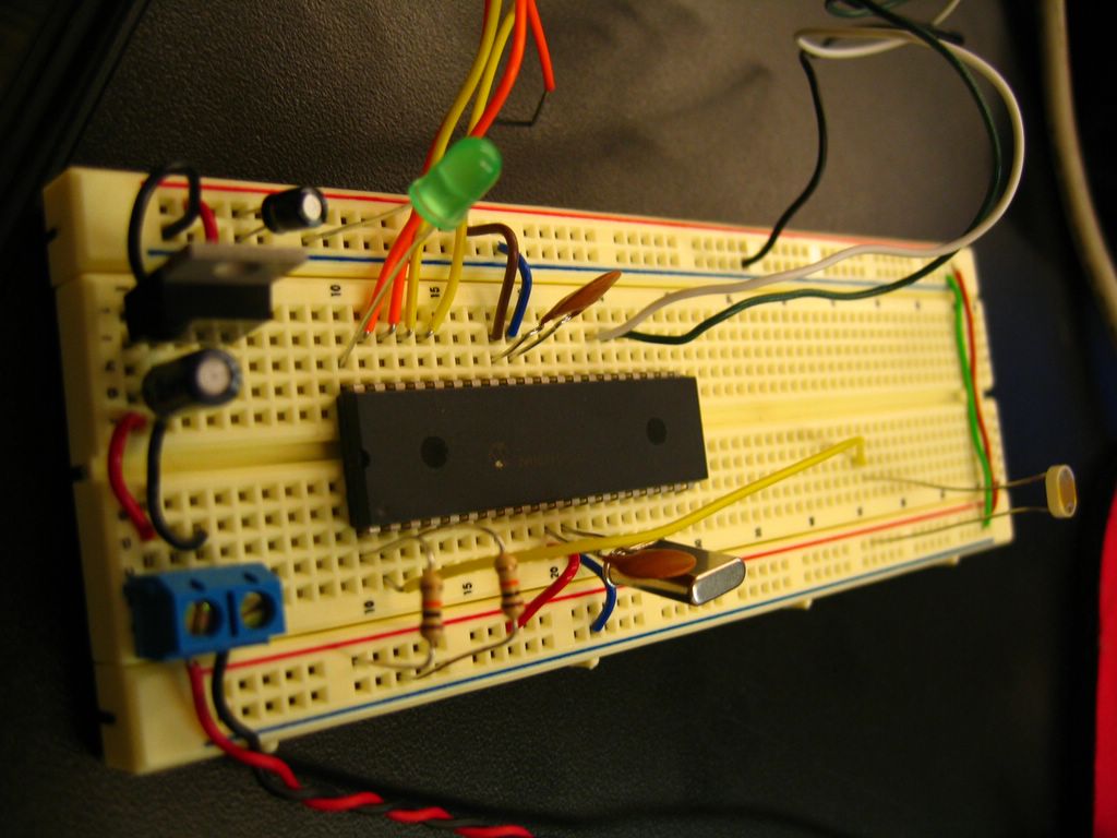
Test circuit

The program ran in MicroCode Studio correctly by changing its output when the input was changed. We are currently stuck on some code in Processing.
In addition, Lazlo mentioned that he wanted a system of 3 switches so that the user would be able to record the music that they were creating, play the music and stop the music, respectively. At first, I thought to use these buttons found on a dismantled portable CD player. After 10 minutes or so of trying to desolder one button, that idea was scrapped. Looking in the junk bin, I found a 3 button switch that Lazlo brought in last semester. It looks like something that would be found in a factory with an assembly line.
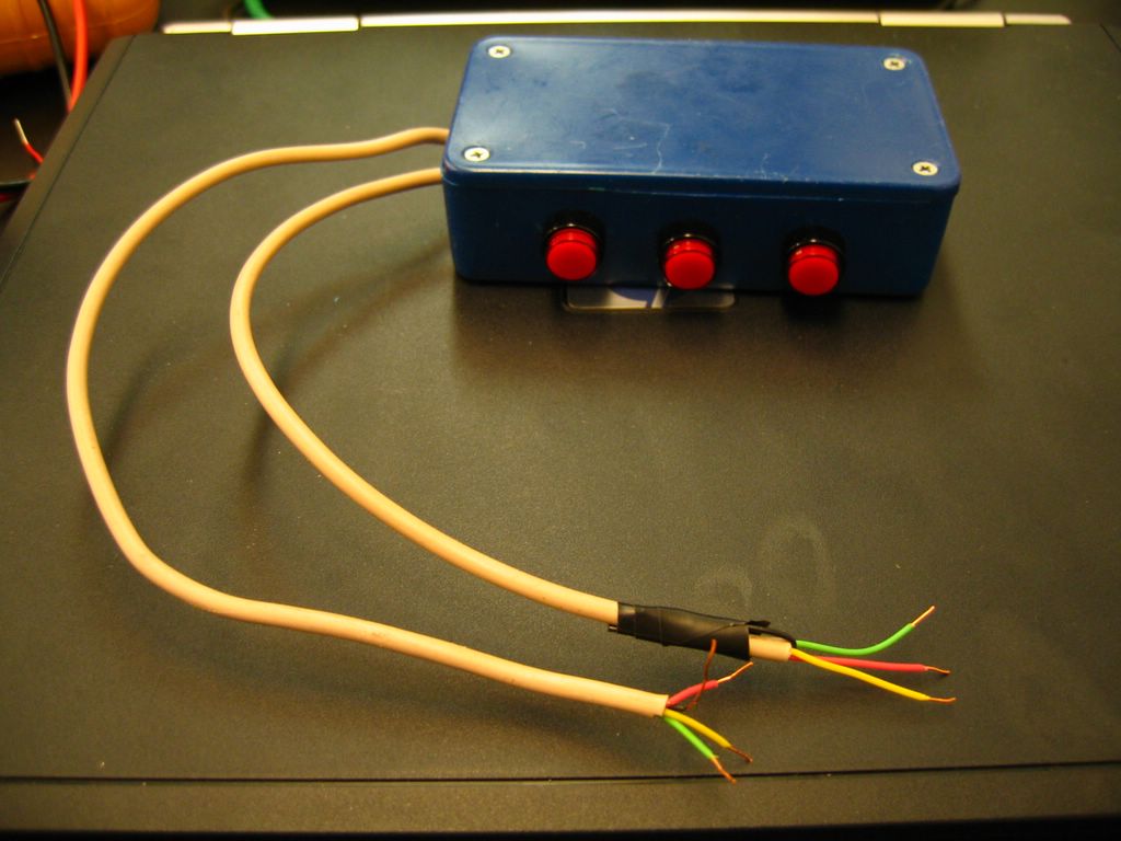
Completed Three Button Switch
We first tried to see if we could just test the wires and see what combination of wires would give us connectivity. It seemed that all combinations did whether or not the button was depressed. My next step was to open the case and see what is making it tick. It wasn't making much sense. There were loads of wire just cross-connected in non-logical ways to all the Archer switches. I decided it was best to desolder and start from scratch.
Several hours later, all of the connections were desoldered. Using a multimeter, it was easy to determine that the upper pins were what controlled the switches on/off. Lazlo said he recalled that the buttons used to light up. It seemed to explain what the other pins were used for. Now all I had to do was figure out how to make these connections such that when the button is depressed, the light on the button would come on. Using alligator clips, a multimeter and my circuit from Assignment #2 I tested a few combination of connections before I had it working.
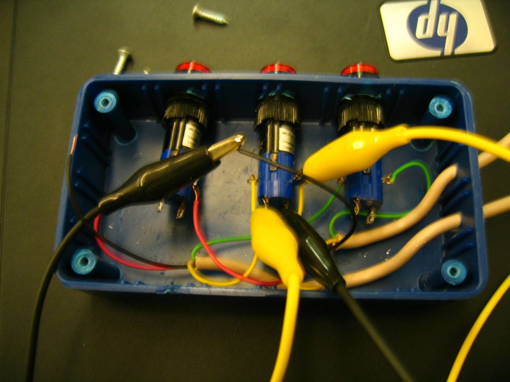
Testing
Finally, I soldered the joints.
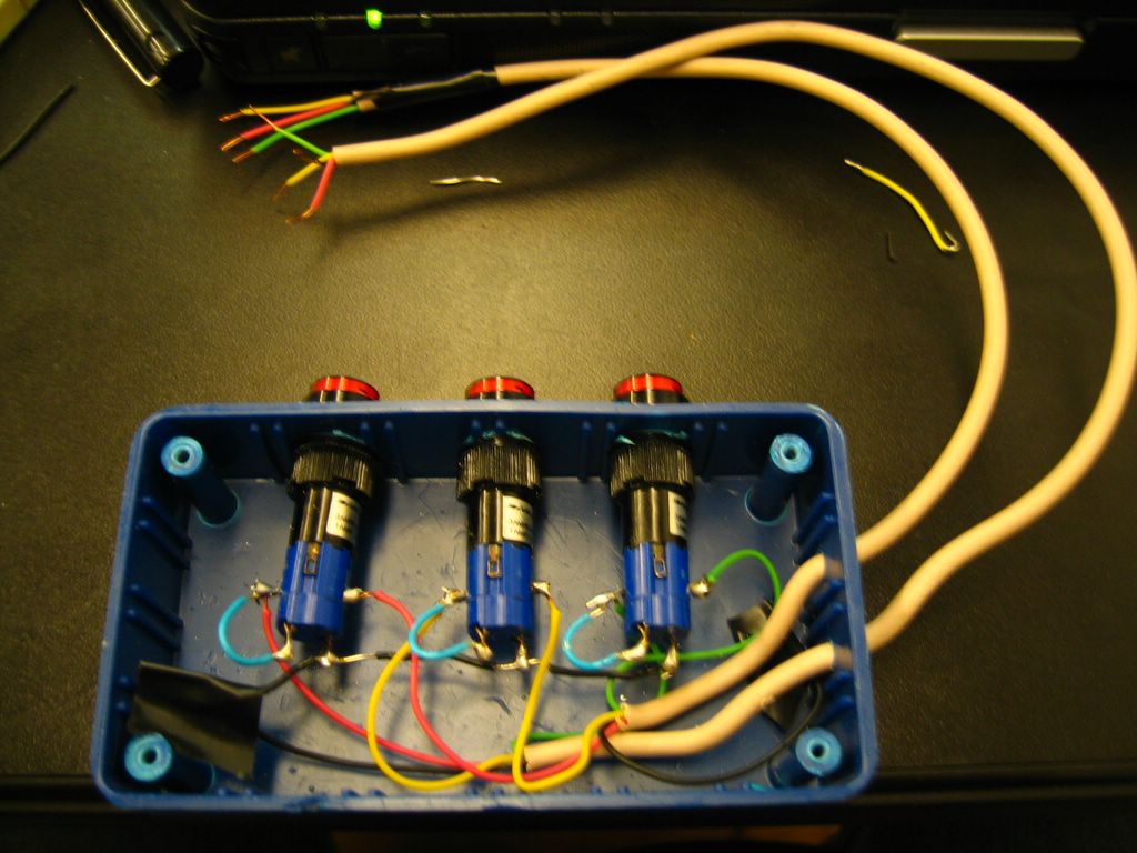
Soldered
So now we have the switch we plan on using. We just need to get the bugs out of the code.
posted by -ellie. @ 7/14/2005 08:24:00 AM
0 comments
![]()
![]()

0 Comments:
Post a Comment
<< Home